Week 14: 14th November to 20th November[]
I continued conducting a few more experiments, the results of which will be included in the CA2 report.
Experiment 4: Transient Response of the System[]
The transient response of each electromagnet is measured by recording a video using a smartphone and embedding a timecode in the video. Using a metric grid printed on a transparent sheet, the height of the spikes is measured. The electromagnet is powered using 4.9 V and 2.3 A of current. The video shows the experiment video taken with timecode embedded.
thumb|300px|left
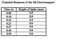
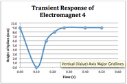
The graphs above plot the height of the spikes up till its maximum height against time during actuation.
The time it takes to reach steady state for Electromagnet 1 is 0.45 s, Electromagnet 2, 0.35 s, Electromagnet 3, 0.38 s, Electromagnet 4, 0.40s, Electromagnet 5, 2.00 s, Electromagnet 6, 0.37s. The time between positioning the sensor above the electromagnet and the sensor (when sensor is detected, height of spikes goes to zero as magnet is switched off) to be detected is 0.05 seconds for Electromagnet 1, 0.05 seconds for Electromagnet 2, 0.12 seconds for Electromagnet 3, 0.10 seconds for Electromagnet 4, 0.20 seconds for Electromagnet 5, 0.23 seconds for Electromagnet 6. It is observed that the delay increases from the 1st to the 3rd and to the 5th electromagnet. The same pattern can be seen from the 2nd to the 4th and to the 6th electromagnet. This can be attributed to the probing sequence used in the current implementation of the system. Electromagnet 1,3 and 5 are probed sequentially when the sensor is positioned above any of them. Likewise for Electromagnet 2,4 and 6, they are probed sequentially when the sensor is positioned above any of them.
Experiment 5: Height of Spikes versus Pulse Width Modulation[]
In this experiment, the Pulse Width Modulation (PWM) of each electromagnet is varied to control the height of the ferrofluid spikes of each of the six “buttons” in the system. The PWM of each electromagnet is varied and a ruler is used to measure the height of the generated spikes.

Figure 19: Using a ruler to measure the height of the generated spikes
The purpose of the experiment is to evaluate the relationship between the PWM and the height of the ferrofluid spikes generated. With the results, the PWM values that correspond to the desired ferrofluid height can be determined. This allows for flexibility in varying the height of the ferrofluid spikes to the desired level during actuation.
The results are as follows:
The relationship between the PWM and the height of the spikes follows an increasing linear trend, suggesting that the system is linearly controllable. However, it is noted that the range of height of the spikes generated is small, with the maximum height at 7 mm for Electromagnet 2 at PWM 100%. As such, the change in height is difficult to discern when the change in PWM value is small. Therefore, the best way to produce a discernible actuation is to turn off the electromagnets completely from PWM 100% to 0% before turning them back on again to PWM 100%.


